Events
Aug 31, 2021
Free Rhino 3D & Grasshopper Tutorial: VR Headset Design

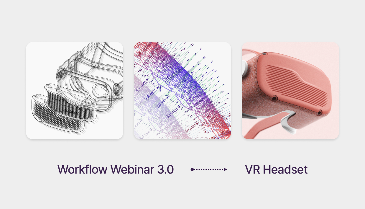
Advanced VR Headset Design: Mastering G2 Curvature & Parametric Textures
Free Rhino 3D & Grasshopper Course | Workflow Webinar 3.0
Welcome to the third module of our free Rhino 3D and Grasshopper course. In this 1.5-hour deep dive, we move beyond basic geometry to tackle a complex consumer electronic product: a VR Headset.
Download Files: cademy.xyz/webinar3
What’s included in this lesson:
- Full Video Tutorial: Follow along with our 1.5-hour step-by-step recording.
- Project Files: Download the exact Rhino and Grasshopper files to practice.
- Expert Workflow: Learn techniques used by leading industrial design firms.
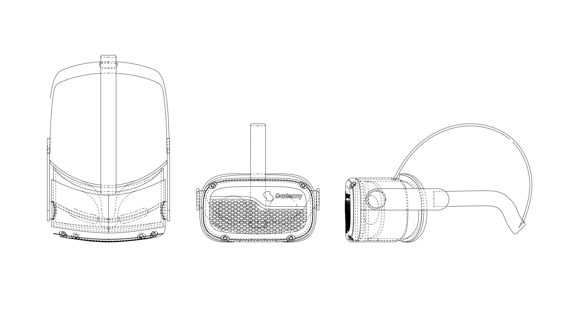
Step 1: 3D Modeling the Base Geometry
- Front Profile: Draw the Front Curve Profile based on technical dimensions.
- Continuity: Use the BlendCrv Command to create G2 curve continuity between profiles.
- Symmetry: Mirror the curve twice to complete the perfectly symmetrical profile.
Step Step 2: Surface Creation & Solid Geometry
- Boundary to Surface: Convert the Curve Boundary into a surface.
- Refining Topology: Rebuild the Surface as a Degree 6 surface in both U & V directions for maximum control.
- CV Manipulation: Move Control Vertices (CVs) to flex the surface for better organic shaping.
- Volumetric Modeling: Extrude the surface to create a solid, watertight geometry.
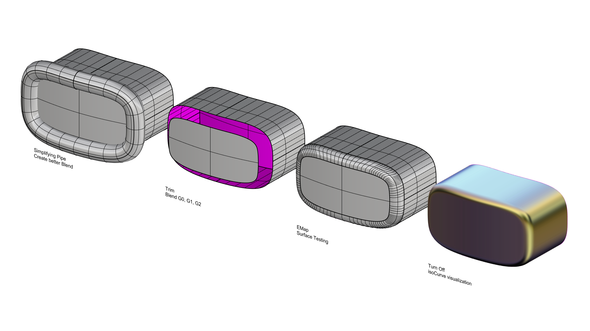
Step 3: Filleting the Edge (Alternative Professional Approach)
This technique is a cornerstone of our free Rhino 3D course, offering a high-end alternative to standard filleting:
- Reference Pipe: Pipe the edge to create a reference surface for trimming.
- Simplification: Rebuild the pipe surface to reduce complexity and ensure smoothness.
- G2 Blending: Use the pipe to trim the edges and bridge the gap using BlendSrf with G2 continuity for a seamless, professional transition.
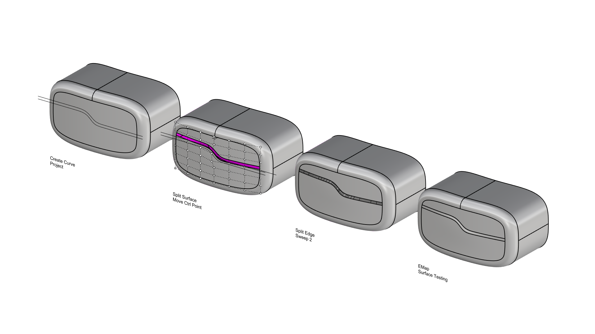
Step 4: Adding the Front Design Feature
- Parallel Layout: Draw two parallel curves on the front face.
- Patch Splitting: Split the front surface patch along these curves.
- Detailing: Move central control points for subtle ergonomic adjustments.
- Curvature Bridges: Use Sweep2 Rails to bridge surfaces, ensuring curvature continuity.
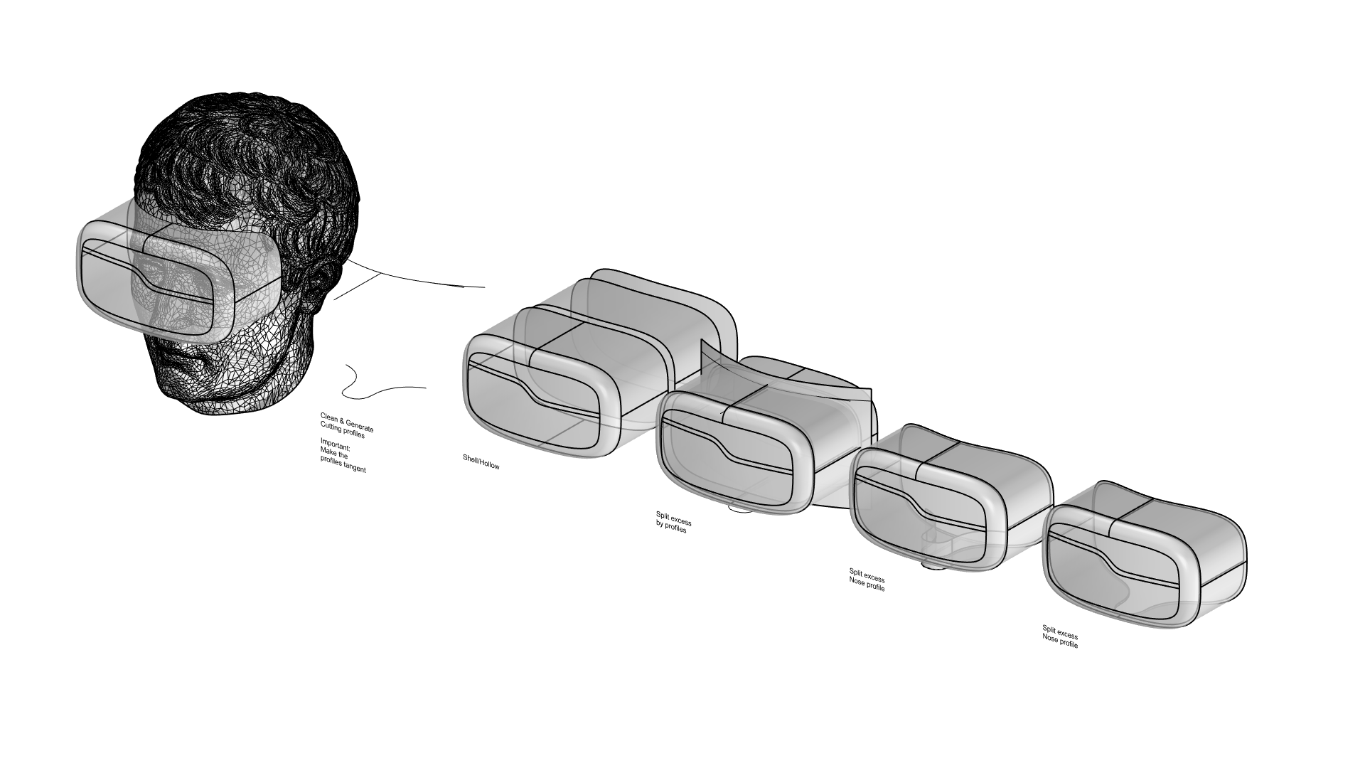
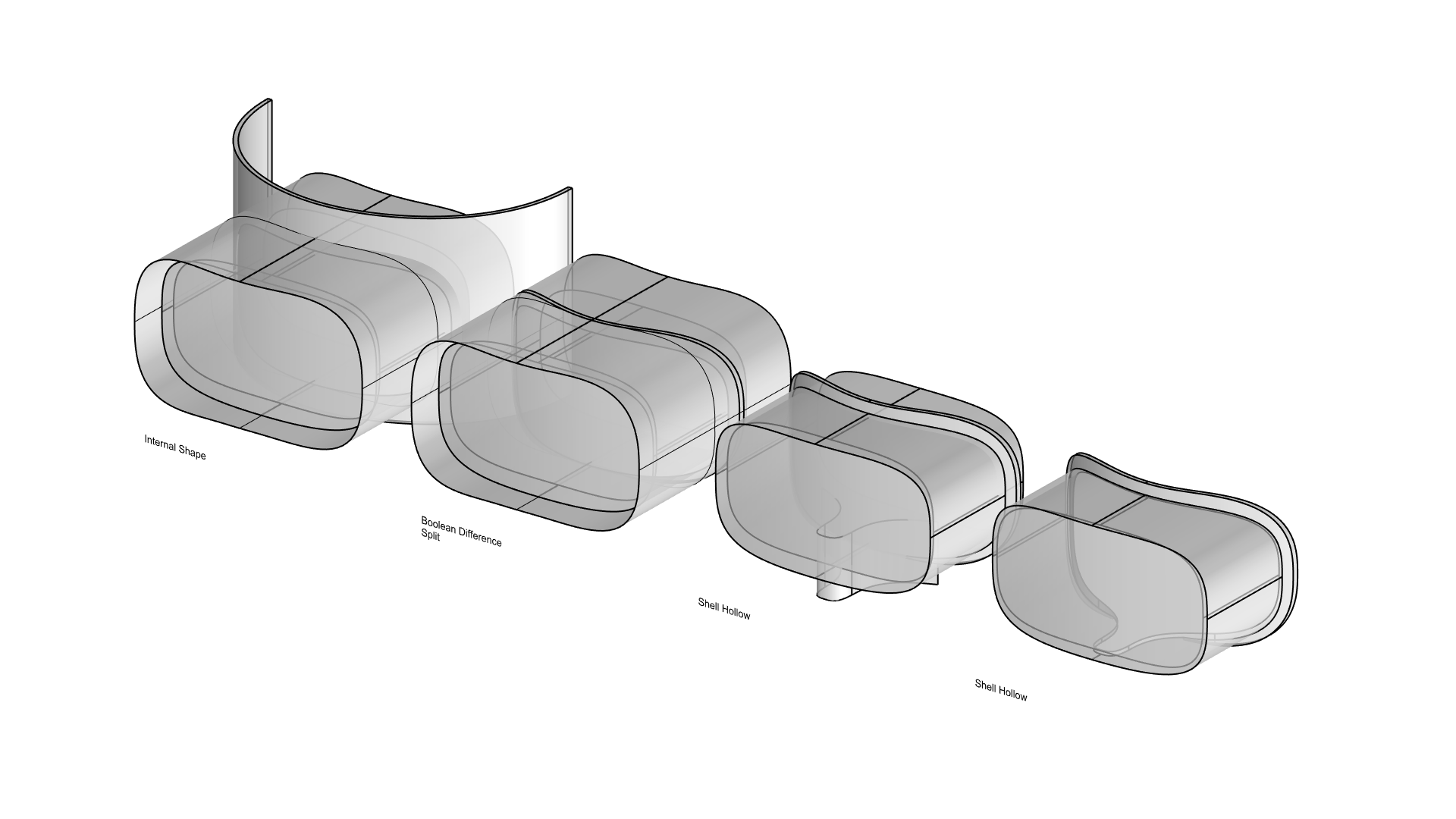
Step 5: Refining the VR Headset Shape
- Mesh Reference: Use mesh geometry to approximate the intersection with the headset.
- Ergonomic Curves: Extract rough splitting curves for forehead, cheek, and nose contact points.
- Precision Cutting: Recreate a clean cutting profile for final detailing.
- Shelling: Offset the outer shell shape to create the internal structure
- Consistency: Use similar splitting profiles to maintain design language consistency.
Step 6: Modeling the Headband
This part of the free Rhino 3d tutorial focuses on organic swept geometry:
- Profile Sketching: Sketch a rough headband profile based on a reference mesh.
- Cross-Sections: Draw a cross-sectional profile for the band.
- Sweep1 Execution: Use the Sweep1 Command to generate the 3D headband geometry.
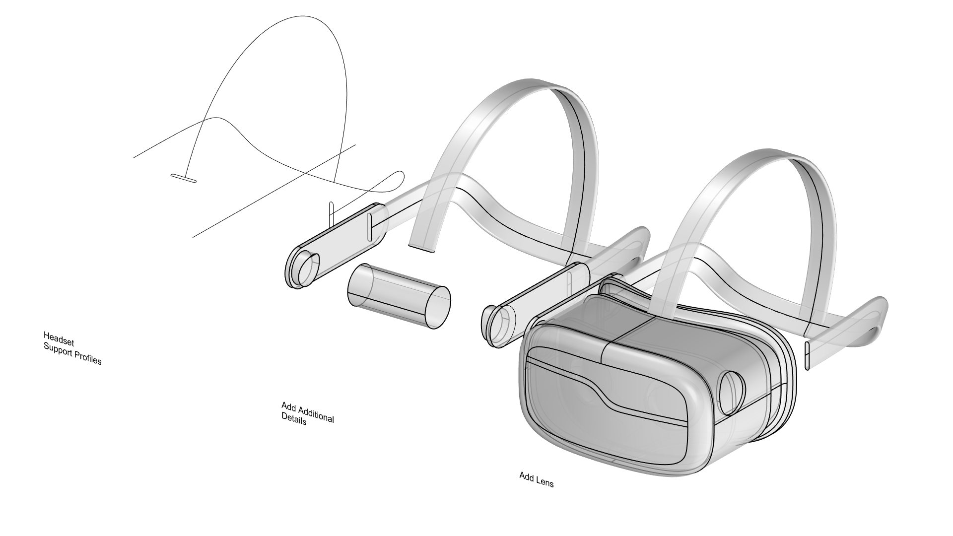
Step 7: Adding Tracking Cameras
- Normal Extraction: Extract the Normal Direction of the surface on four reference points.
- Pulling Geometry: Split the surface using a circular curve pulled to the blend surface.
- Lens Extrusion: Use the same Normal Vector to extrude the camera lenses into position.
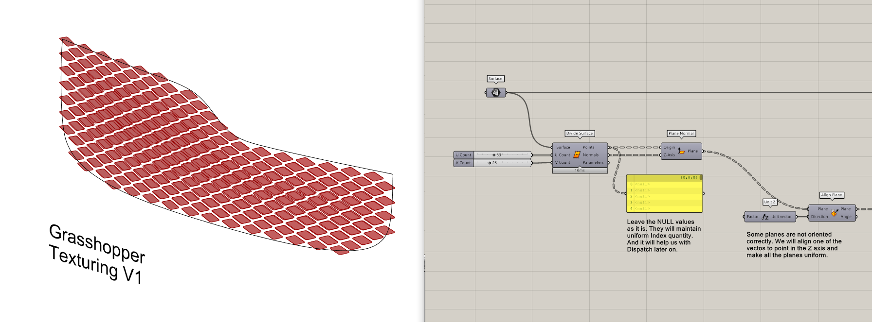
Step 9: Applying Parametric Texture in Grasshopper 3D
This module of our free Grasshopper 3D course covers two specific algorithmic patterns:
- Pattern 1: Diamond Paneling
- Create a Grid of Points & Planes on the surface.
- Align the Frames to the Z-Axis for correct orientation.
- Generate Rectangles and rotate them 45°.
- Apply Non-Uniform Scaling along the local X & Y axes.
- Extrude Diamond Curves along the Surface Normal.
- Control depth dynamically using an Edge-Based Attractor Curve.
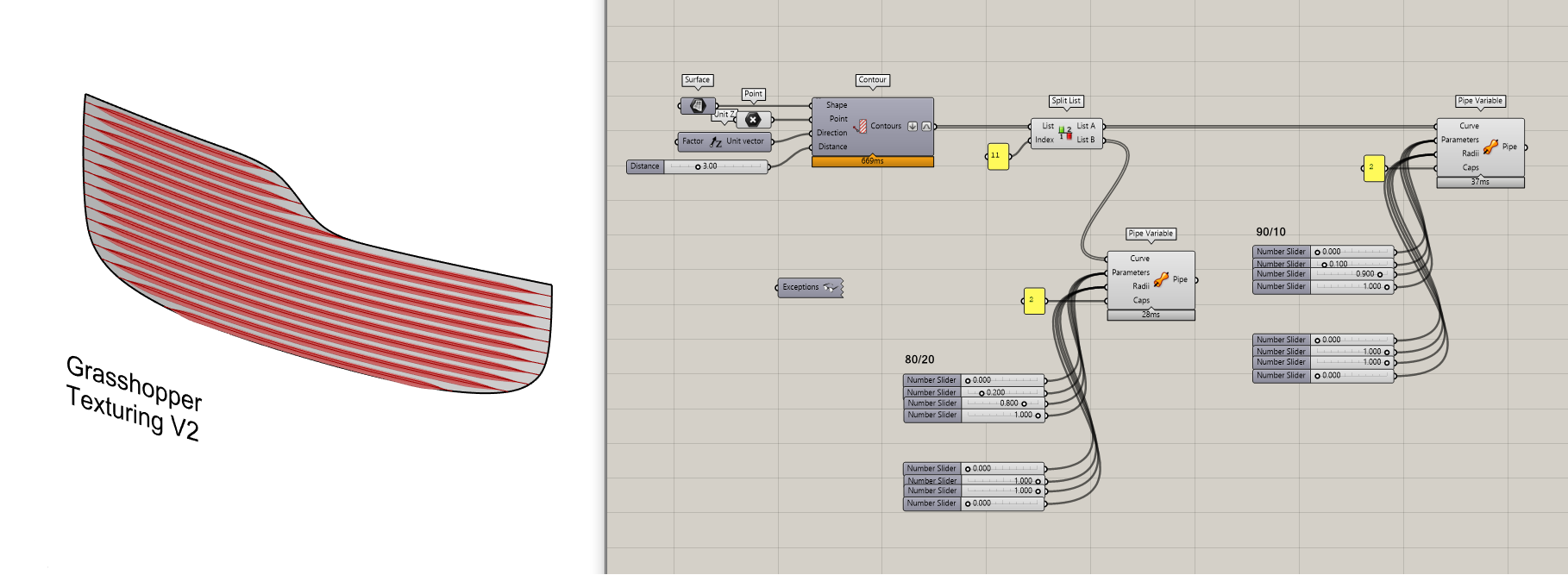
- Pattern 2: Diamond Paneling
- Create horizontal cross-sections using the Contour Component.
- Convert curves to Variable Pipes with thickness variation.
- Reparameterize the curves between 0 and 1 to control thickness flow.
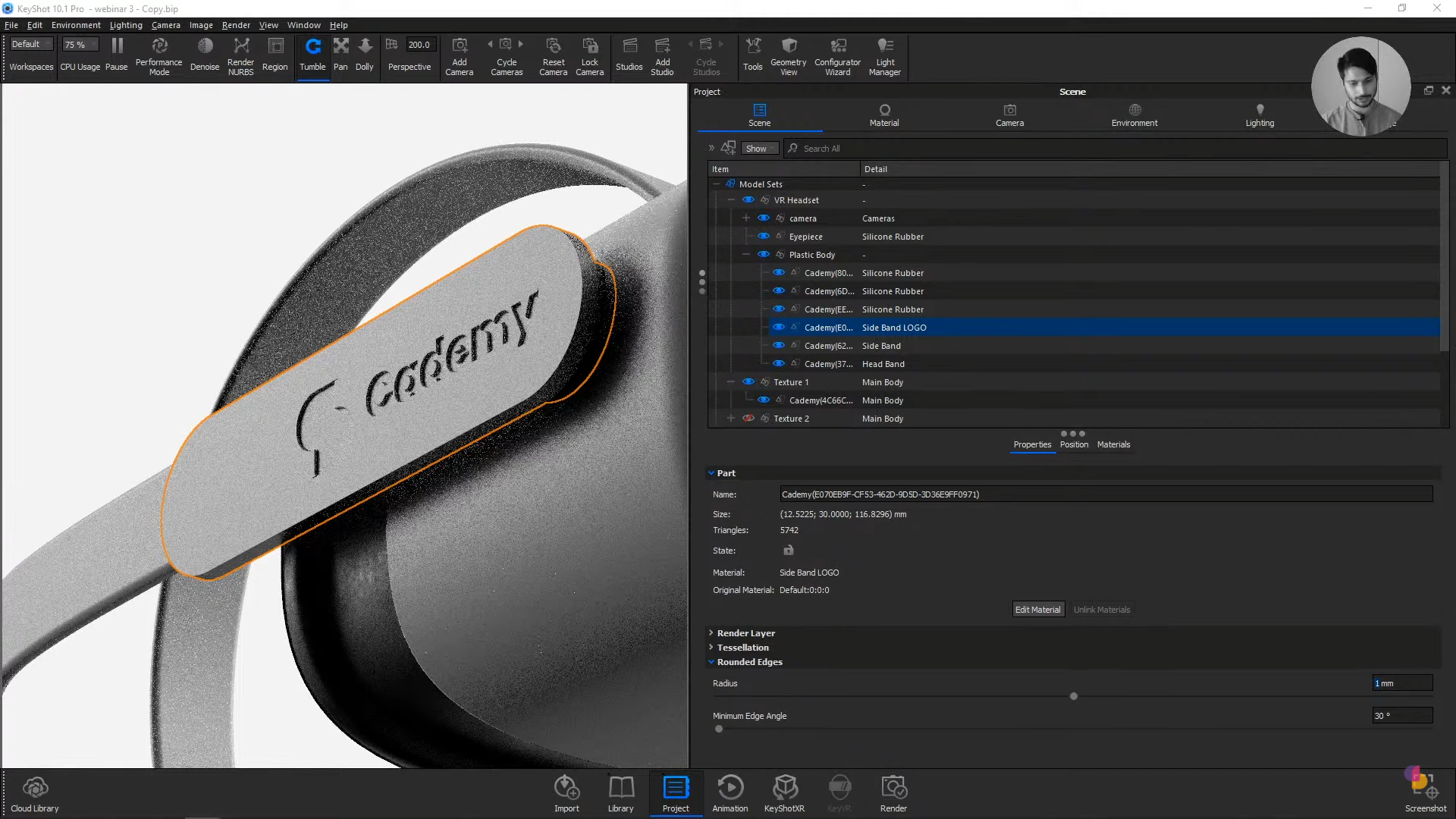
Step 10: Rendering in Keyshot
- Import: Open the native
.3dmfile in KeyShot. - Materials: Apply high-fidelity materials from the library.
- Lighting: Set up a professional 3-Point Light environment.
- Displacement: Add a logo using a Displacement Geometry Node for realistic 3D depth.
Thank you for reading ❤️
