Events
Feb 3, 2025
POC Helmet & Gyroid Lattice Design: Free Rhino 3D & Grasshopper Tutorial

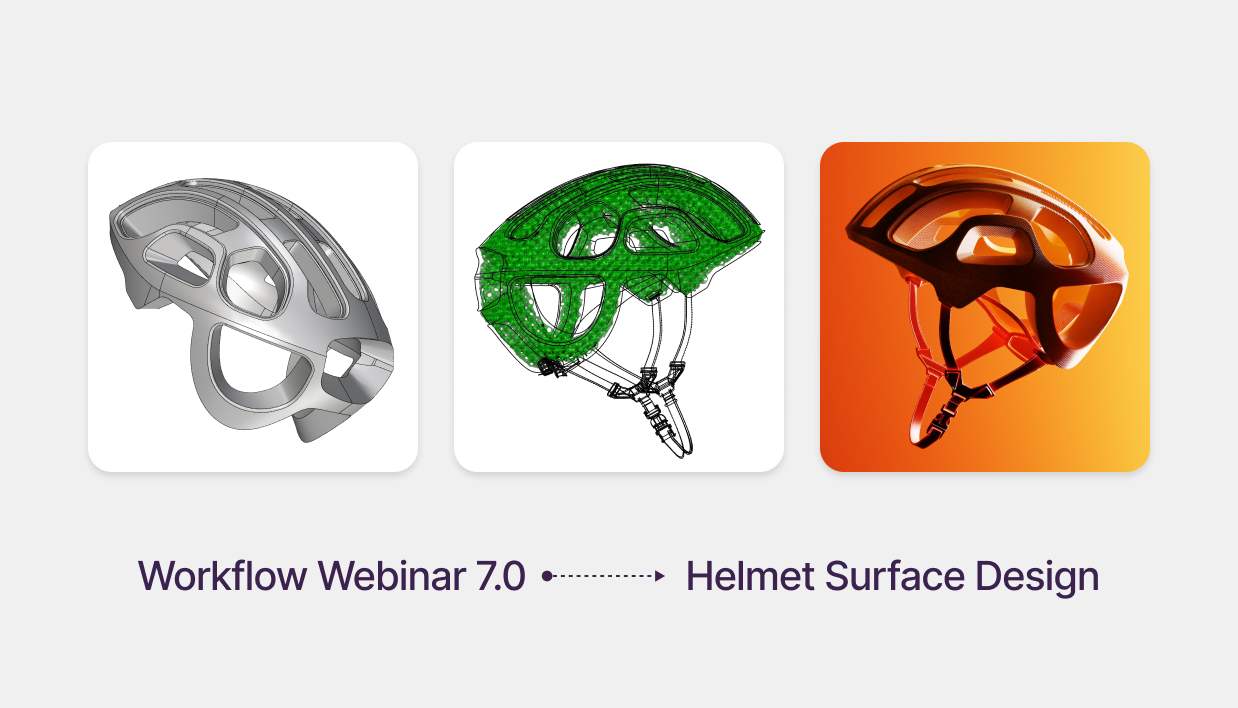
Advanced Product Design: Modeling a POC Helmet with Gyroid Lattices
Free Rhino 3D & Grasshopper Course | Workflow Webinar 7.0
Welcome to the seventh module of our free Rhino 3D and Grasshopper course. In this 1.5-hour advanced session, we explore the cutting-edge workflow used in high-performance protective gear. You will learn to transform a raw 3D scan into a high-quality NURBS model, achieving Class A surface quality in Rhino before generating complex impact-absorbing lattices in Grasshopper.
Download Files: cademy.xyz/webinar7
What’s included in this lesson:
- Full Video Tutorial: Follow along with our 1.5-hour step-by-step recording.
- Project Files: Download the exact Rhino scan data and Grasshopper files to practice.
- Advanced Engineering: Learn to create functional internal structures for 3D printing and manufacturing.
What you will learn in this module:
- 3D Scan to Surface Workflow: How to import scan data and use MeshOutline to extract clean silhouette curves for rebuilding.
- Class A Surfacing in Rhino: Utilizing Degree 4 single-span curves and Match Surface commands to ensure G2 curvature and perfect highlights.
- Global Edge Continuity: Using specialized plugins to verify surface quality and ensure your model is a watertight solid.
- Gyroid Lattice Generation: Leveraging the Crystallon and Dendro plugins in Grasshopper to create algorithmic, impact-absorbing structures.
- Cinematic KeyShot Animation: Mastering Part Fade and Cutaway Materials to professionally showcase internal design features in your portfolio.
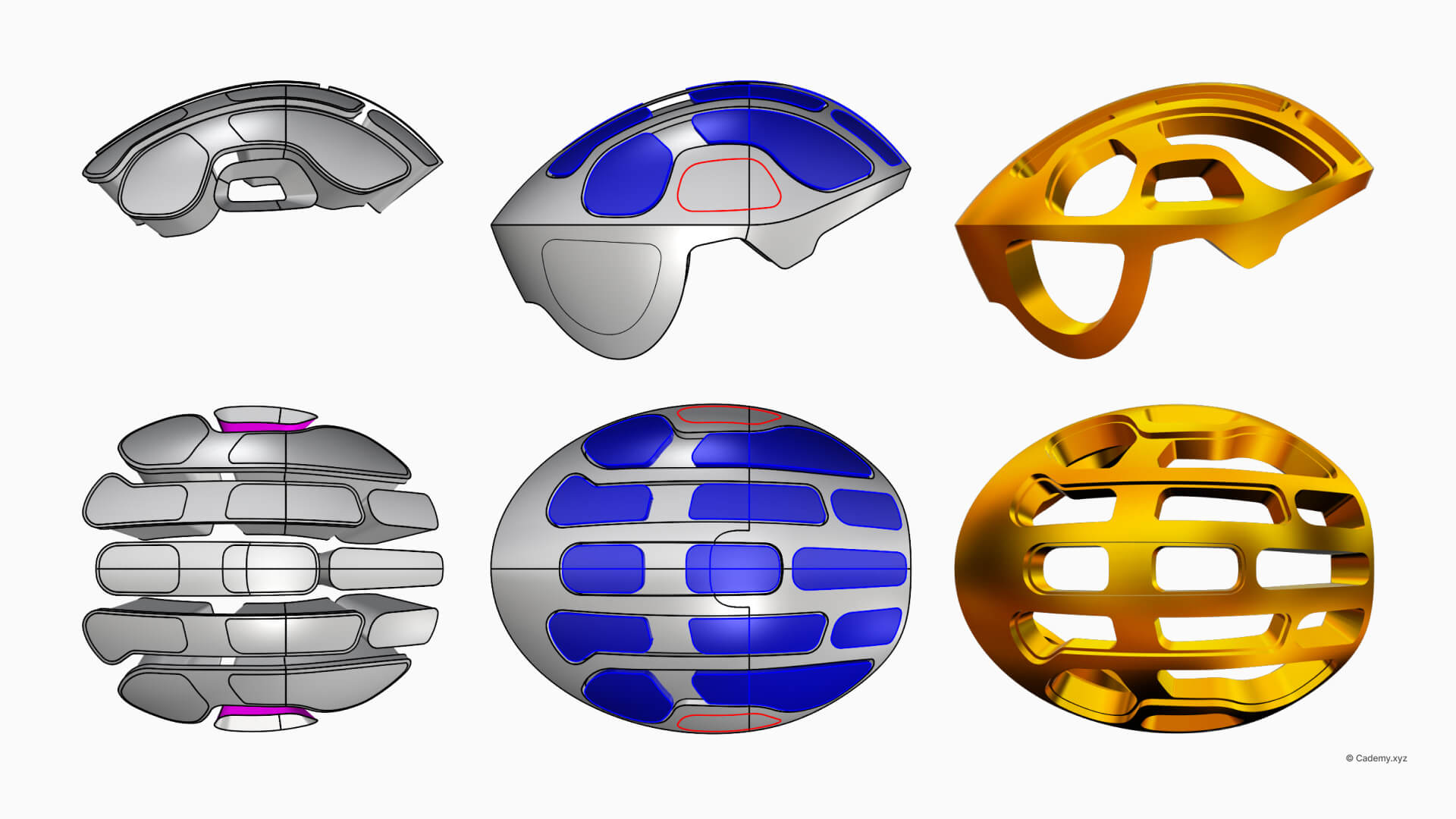
Step 1: Building the Helmet in Rhino
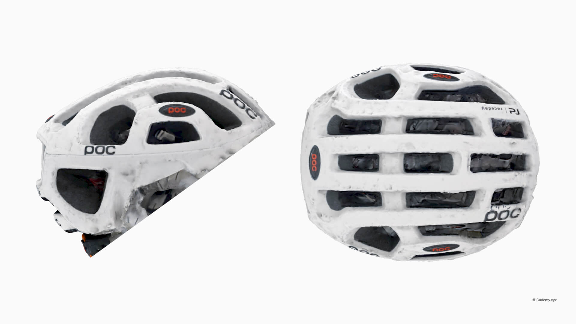
Importing the 3D Scan & Creating Primary Curves
- Import the 3D scan and use MeshOutline to extract the primary silhouette.
- Create Degree 4 single-span curves for maximum smoothness and control.
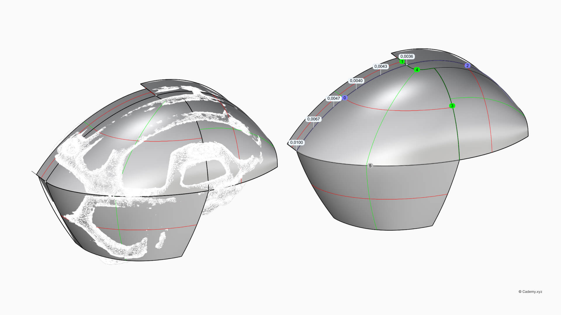
Generating Primary Surfaces
- Generate primary surfaces using the Surface from 4 Edges command.
- Refine tangency and curvature using Match Surface for a Class A finish.
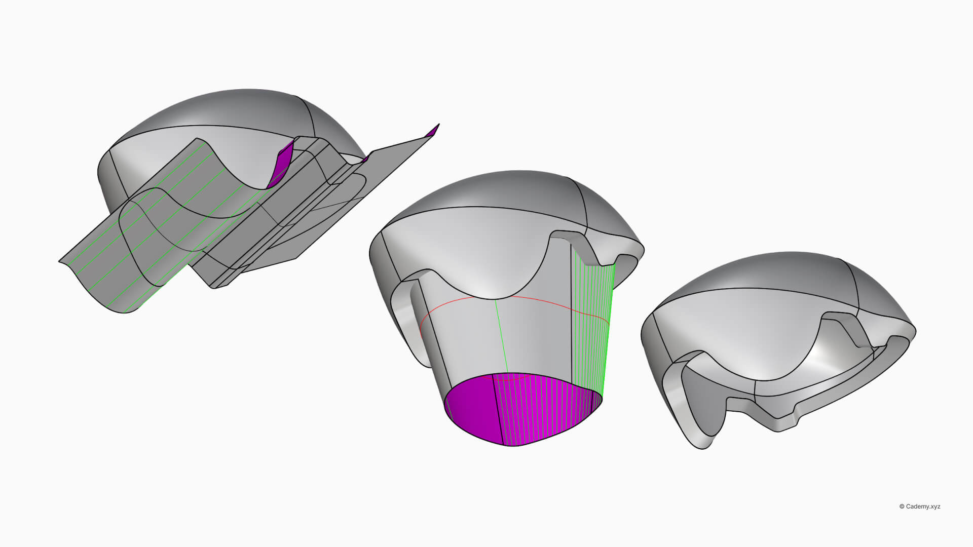
Converting to a Solid Model
- Connect the front face and blend edges for seamless continuity.
- Scale and thicken the model to ensure 3D printing compatibility.
Step 2: Perforations & Bottom Features
Designing Vent Holes
- Use CurveBoolean to define complex, organic vent profiles.
- Apply fillets and offsets to ensure smooth, manufacture-ready edges.
- Project and trim the vents onto the helmet's NURBS surface.
Refining the Bottom Section
- Duplicate and scale the bottom edges to reinforce the structural integrity.
- Use a Global Edge Continuity check to ensure a watertight solid ready for fabrication.
Step 3: Creating Gyroid Lattices in Grasshopper
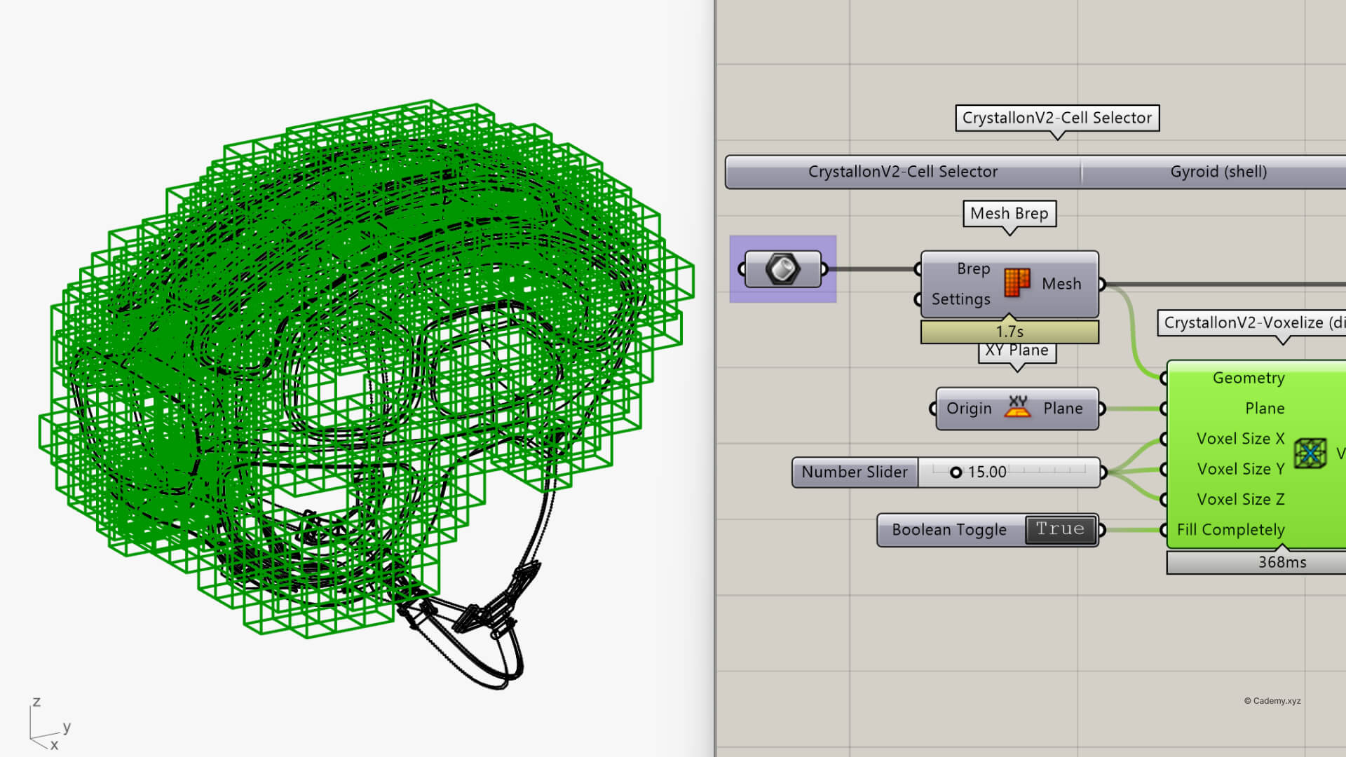
Preparing the Mesh for Lattice Generation
- Convert the NURBS model into a mesh for parametric design.
- Define a Voxel Grid (20x20x20mm) for precise lattice distribution within the helmet.
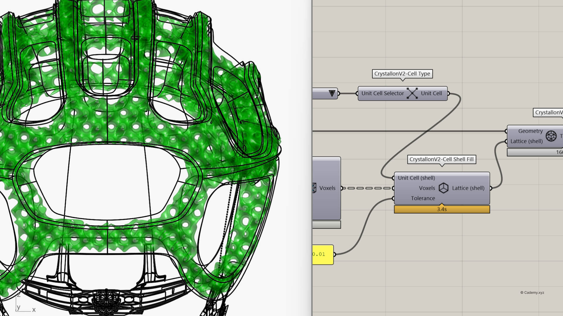
- Generate a Gyroid Lattice using the Crystallon plugin.
Refining the Structure
- Thicken the lattice using Mesh Thicken and apply Catmull-Clark Subdivision via Weaverbird.
- Finalize the structure for STL export, optimized for SLA and FDM 3D printing.
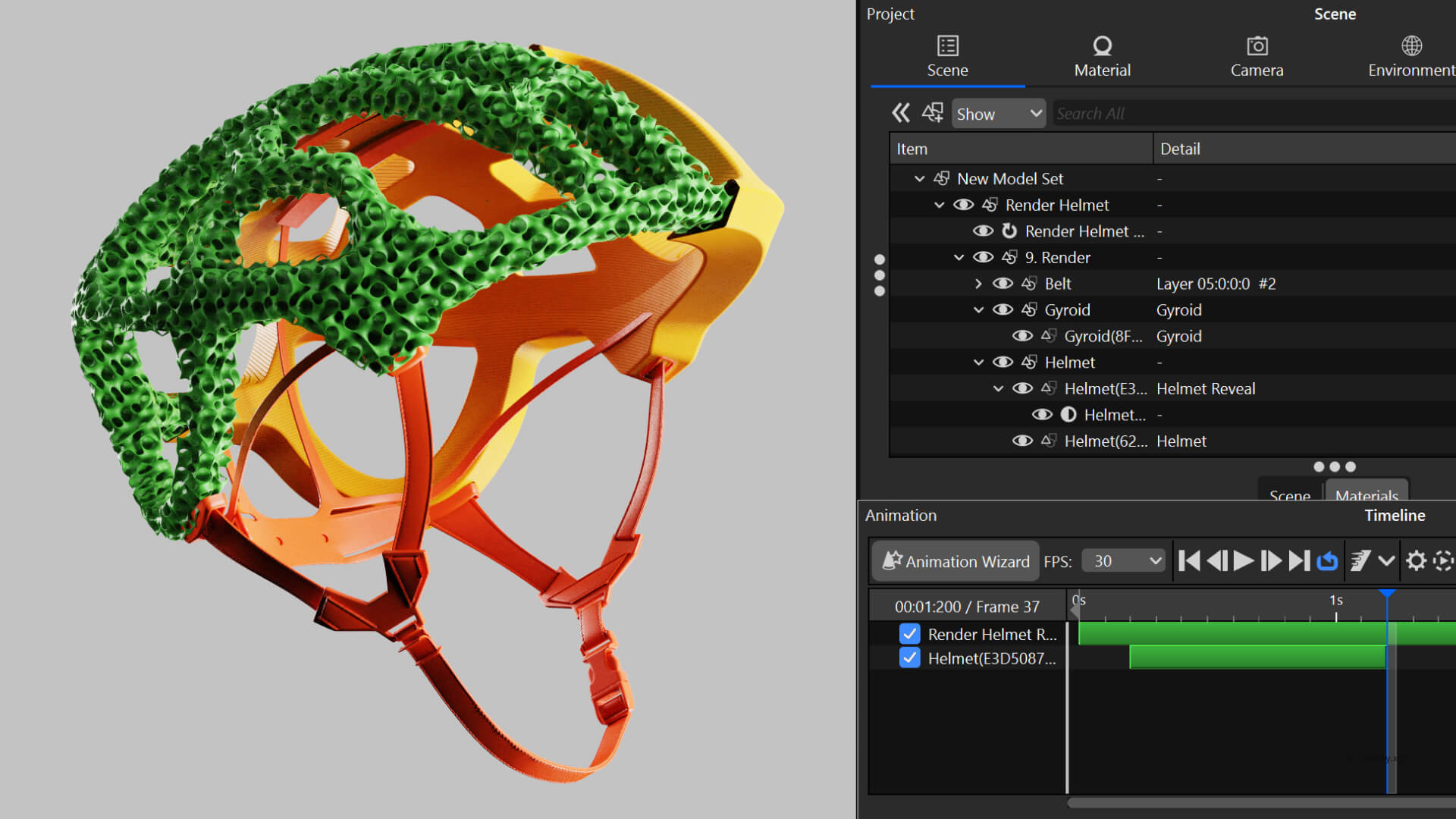
Step 4: Rendering & Animation in Keyshot
Setting Up the Scene
- Import the native Rhino model and apply realistic glossy and matte materials.
- Adjust HDRI lighting to emphasize the depth of the vent holes and lattice.
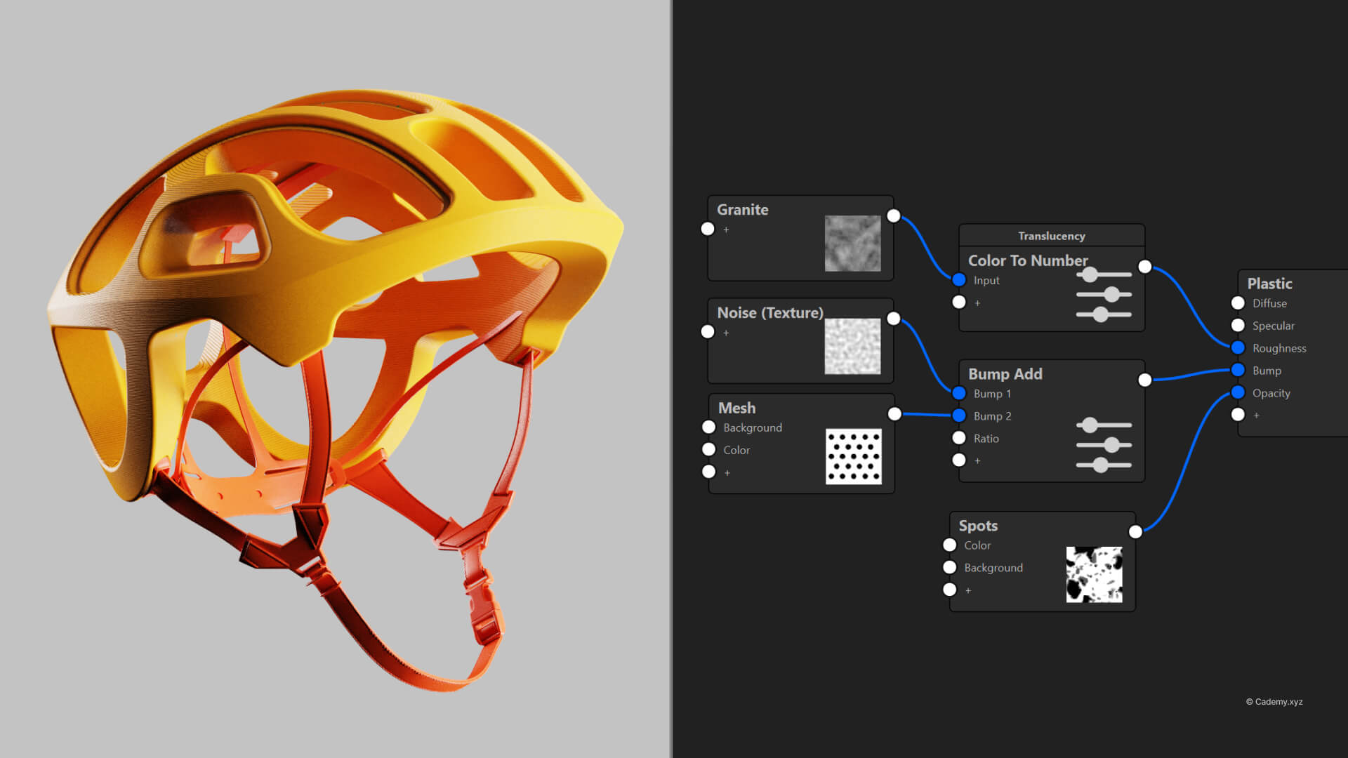
Animating the Reveal
- Set up a Part Fade Animation to unveil the internal structures.
- Create a Cutaway Material view for a dynamic, professional cross-section presentation.
The result? A polished, presentation-ready render highlighting both form and function.
Tools & Plugins
- Software: Rhinoceros 3D, Grasshopper 3D, KeyShot.
- Plugins: Global Edge Continuity, Weaverbird, Dendro, Crystallon.
- Manufacturing: Optimized for high-fidelity 3D printing and industrial prototyping.
Thanks for reading ❤️
