Anatomy of a Parametric Pattern: Grasshopper 3D Texture Logic

Anatomy of a Parametric Pattern: A 6-Step Guide for Industrial Designers
Most beginner Grasshopper 3D users lack a clear understanding of the underlying anatomy of a pattern. To transition from basic tutorials to professional product design and manufacturing, you must master the fundamental logic of how a pattern is structured within the Grasshopper environment.
Pro Tip: If you want to master the skill of applying textures to complex, non-uniform surfaces (polysurface), check out our Parametric Texture Workshop.
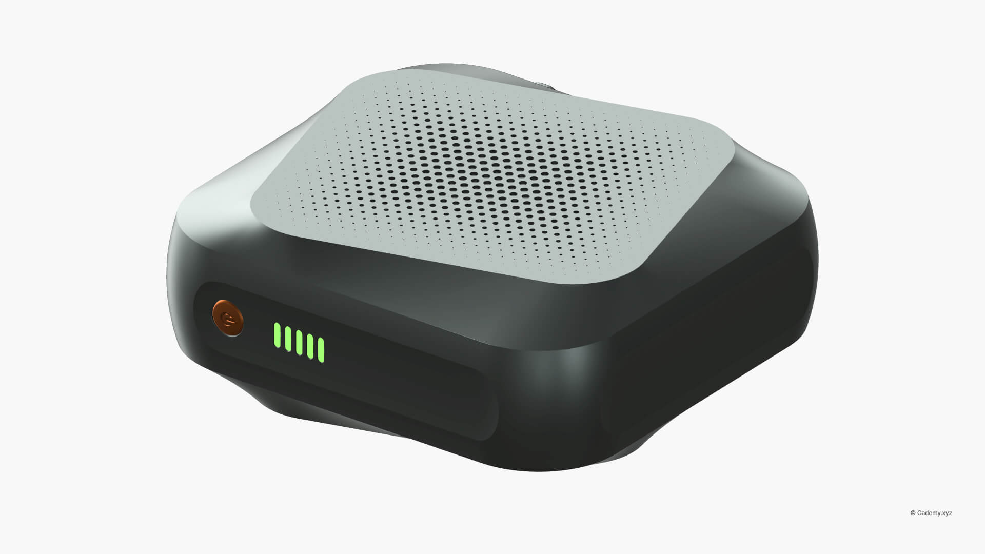
Whether you are designing a high-performance sneaker sole or a premium speaker grille, this 6-step framework ensures your design is functional, parametric, and manufacturable. Let's look at this battery pack designed by our Rhinoceros Masterclass Student Mustafa Kamaludeen.
Step 1: Preparing the Target "Skin"
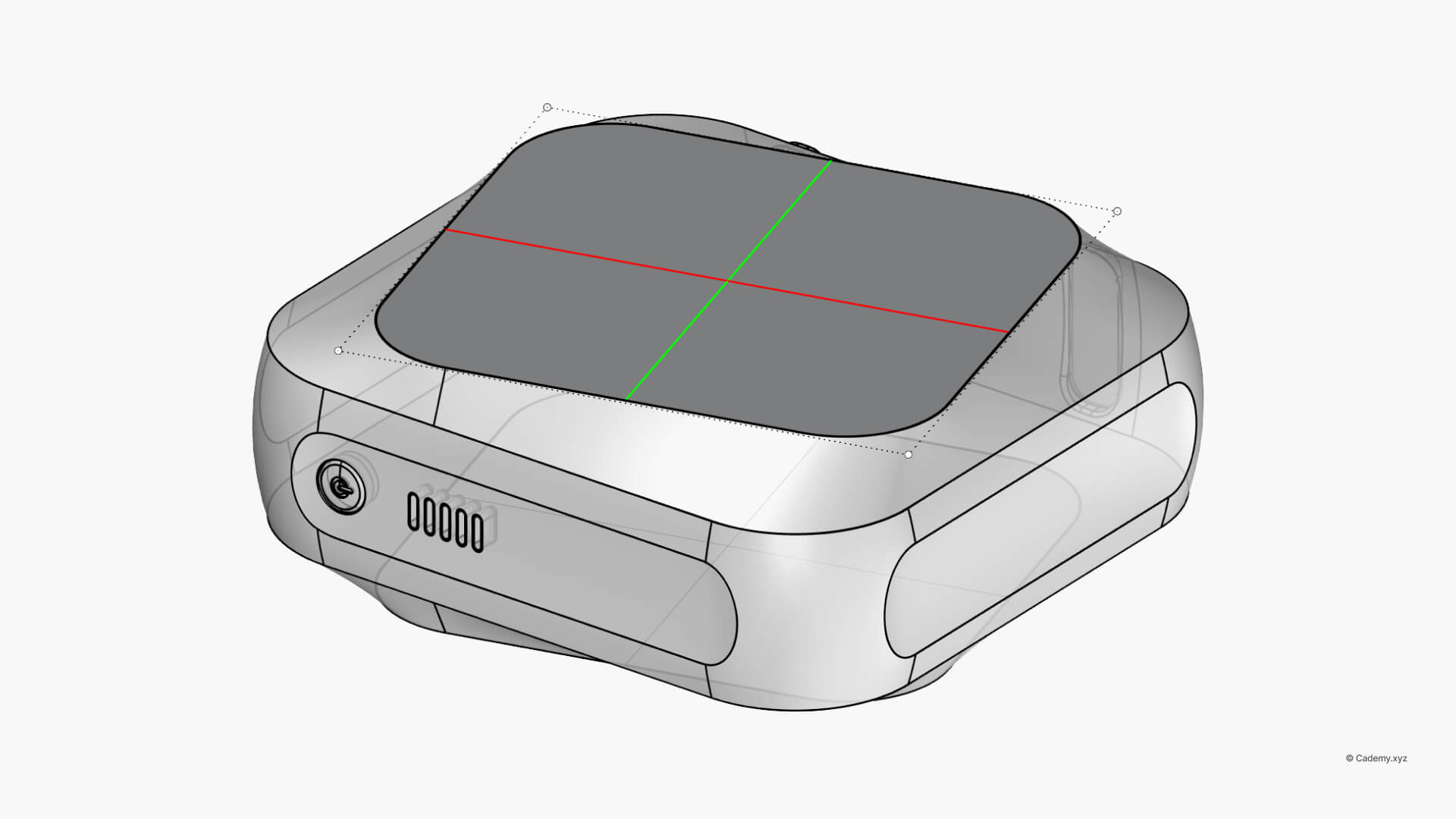
Before applying any texture, you must prepare the foundation. Depending on your design, you may need to orient the part or convert a complex polysurface into a single, clean surface.
Step 2: Making the Placeholder Grid
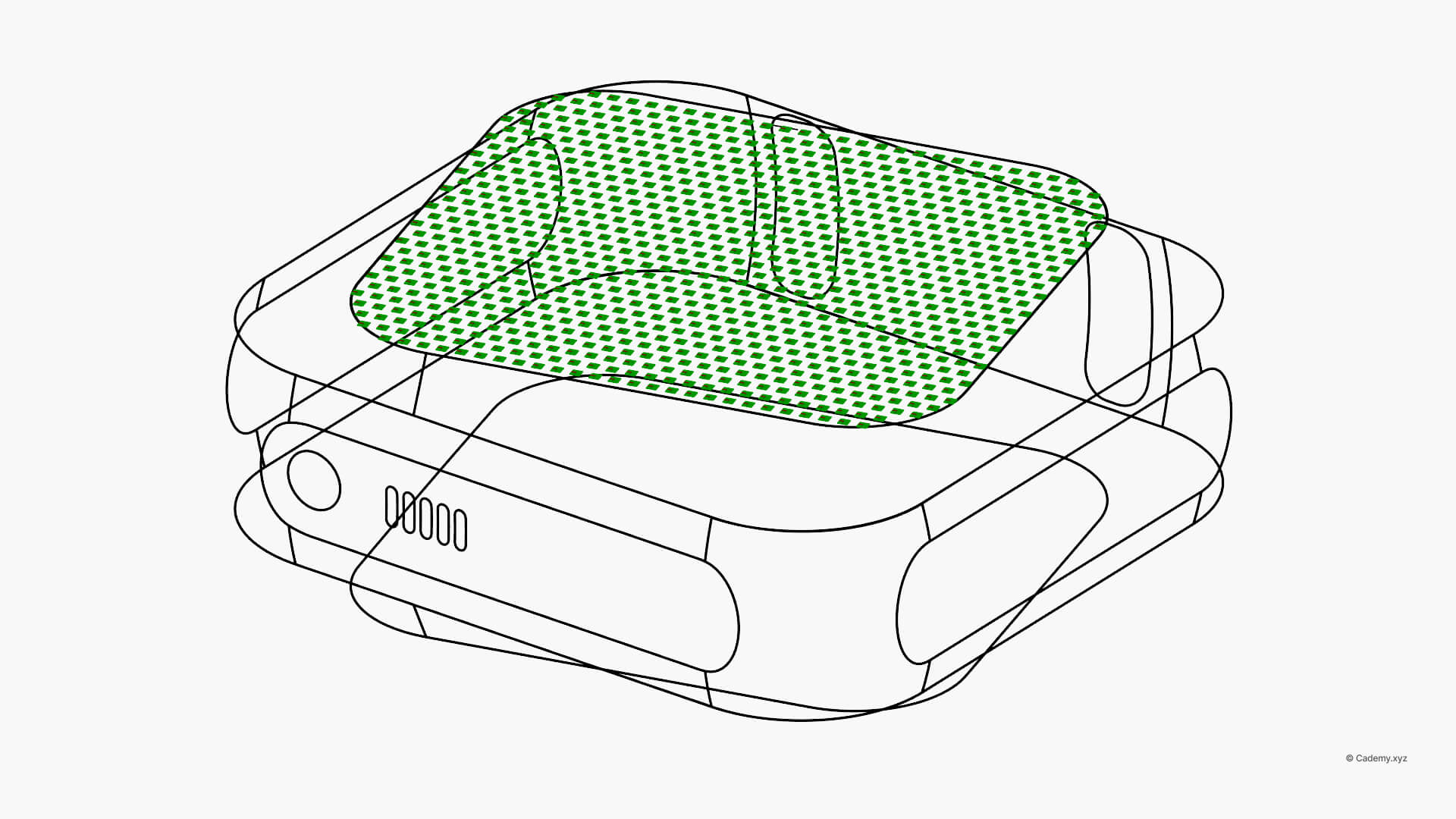
The grid acts as your digital scaffolding. You can generate a Square, Hexagonal, or Staggered grid either on a custom plane or directly onto the target surface. These cells serve as the "placeholders" where your texture panels will eventually live.
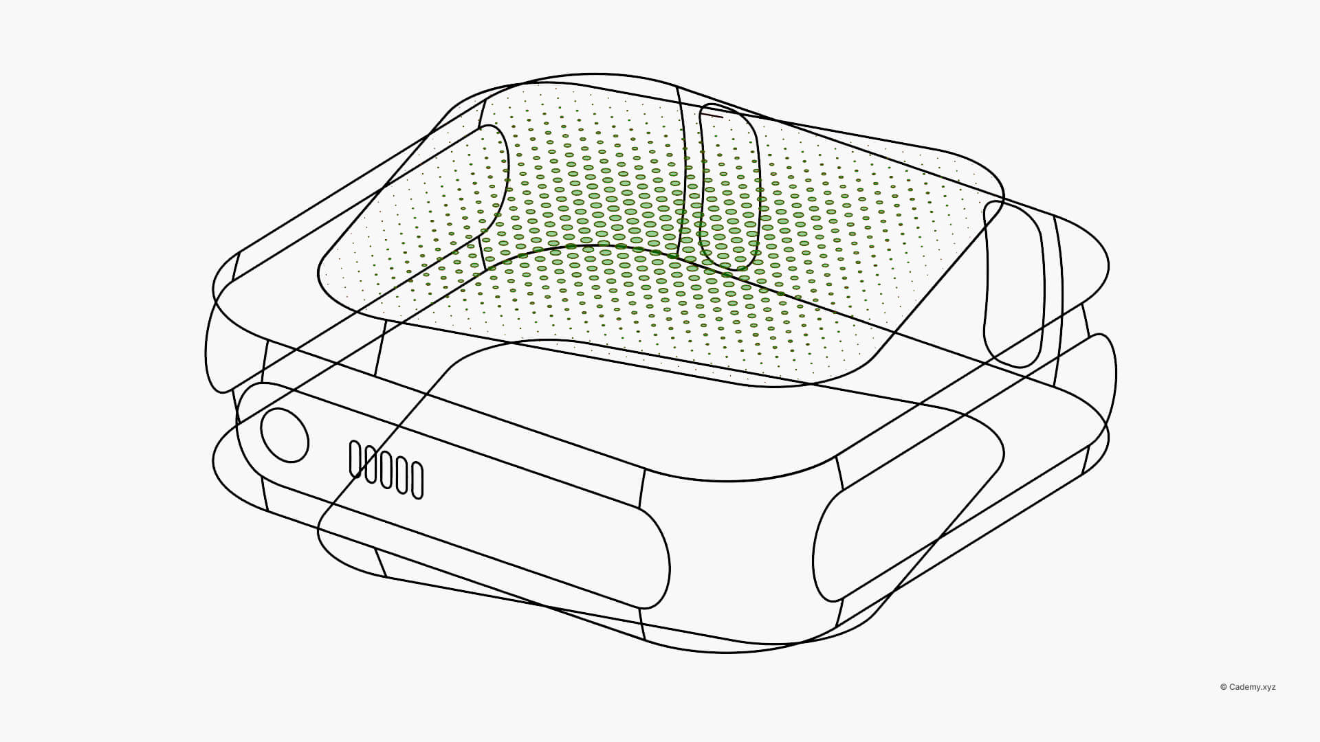
Step 3: Defining the Attractor Influence
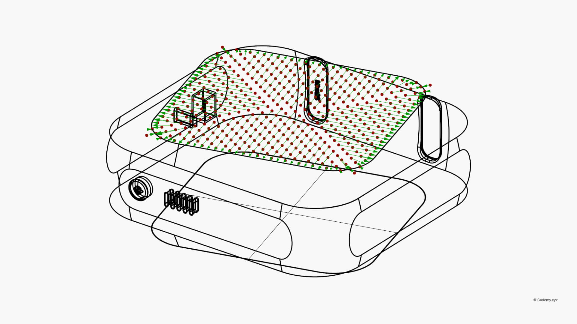
This is the "brain" of your pattern in Grasshopper 3D. By using points, curves, or boundaries, you create an attractor effect. This allows the pattern to fade, scale, or change properties based on its distance from your specified geometry.
Step 4: Remapping for Design for Manufacturing (DfM)
This is the most critical step in any Grasshopper 3d course. Raw distance data is often too large to be used directly as a geometric property.
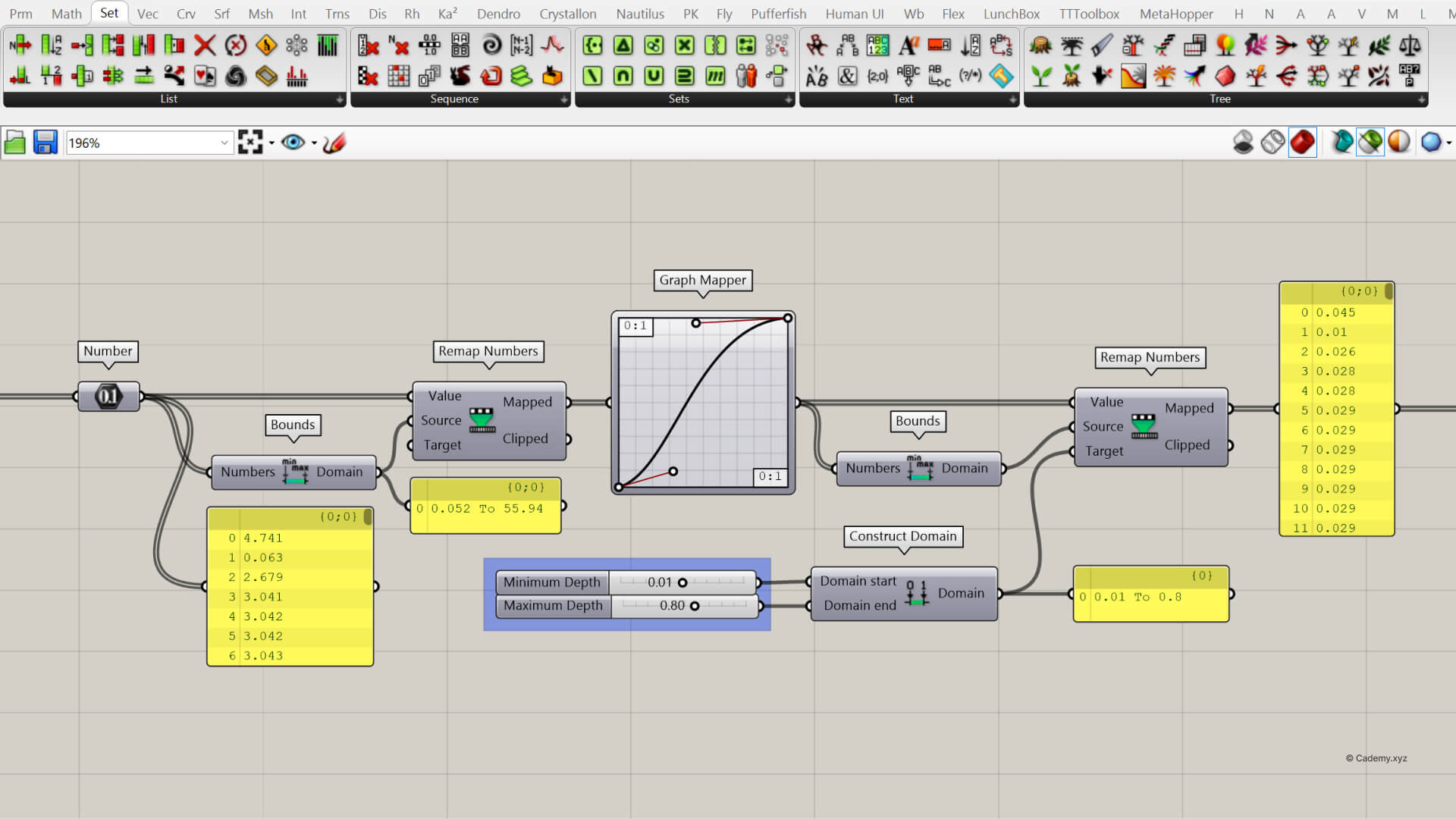
Why we use Remap Numbers?
Imagine your attractor point is 78mm away. If you use "78" as a hole radius, the pattern will break. By remapping numbers, you can "squash" that raw data into a specific range—for example, between 2mm and 5mm—ensuring it fits your manufacturing constraints perfectly.
Step 5: Deploying Texture Geometry
With your grid ready and your DfM values calculated, it’s time to generate the actual geometry. Whether you are using simple circles or custom-modeled modules, the geometry will now respond dynamically to your remapped data.
Step 6: The Final Transfer & Integration
The final step is to unify the texture with your part. Depending on your texture type, you will perform a Solid Union, Boolean Difference, or a Trim and Join. This results in a "water-tight" model ready for 3D printing or CNC machining.
Take Your Skills Further
If you’re looking for a free Grasshopper 3D tutorial or a comprehensive Rhinoceros 3D course, check our Live workshops.
